United States, Arleigh Burke Class Destroyer (DDG-51)
Model
Author: James Harney, LT USN
Class: MV-4204, 23 September
2001
|
|
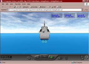
Fig.
2ArleighBurke.wrl (stern view) |
Files Created(Cr)/ Modified (M) / Used (U) for Model:
Directory:
http:\web.nps.navy.mil\~brutzman\Savage\DDG-United
States-ArleighBurke\toc.html
|
(Cr) ArleighBurke.xml |
(Cr)ArleighBurke.wrl |
(Cr) ArleighBurke.html |
|
(Cr) Hull.xml |
(Cr) Hull.wrl |
(Cr) Hull.html |
|
(Cr) FlightDeck.xml |
(Cr) FlightDeck.wrl |
(Cr) FlightDeck.html |
|
(M) Gun.xml |
(M) Gun.wrl |
(M) Gun.html |
|
(Cr) Propellers.xml |
(Cr) Propellers.wrl |
(Cr) Propellers.html |
|
(M) MissileDirector.xml |
(M) MissileDirector.wrl |
(M) MissileDirector.html |
|
(M) Water.xml |
(M) Water.wrl |
(M) Water.html |
|
(Cr) ArleighBurkeGeneric.xml |
(Cr) ArleighBurkeGeneric.wrl |
(Cr) ArleighBurkeGeneric.html |
|
(Cr) Launcers.xml |
(Cr) Launcers.wrl |
(Cr) Launcers.html |
|
|
|
|
|
(Cr) forwardvertrep.jpg |
(Cr) nonskid.jpg |
(Cr) nsflightdeck.jpg |
|
(U) grill.png |
(U) Ocean_3_back.jpg |
(U) Ocean_3_bottom.jpg |
|
(U) Ocean_3_right.jpg |
(U) Ocean_3_front.jpg |
(U) Ocean_3_top.jpg |
|
(U) Ocean_3_left.jpg |
|
|
|
|
|
|
Directory:
http:\web.nps.navy.mil\~brutzman\Savage\Weapons\Missiles\toc.html
|
(Cr) HarpoonPrototype.xml |
(Cr) HarpoonPrototype.wrl |
(Cr) HarpoonPrototype.html |
|
(Cr) TomahawkPrototype.xml |
(Cr) TomahawkPrototype.wrl |
(Cr) TomahawkPrototype.html |
|
(Cr) MissileExplosionPrototype.xml |
(Cr) MissileExplosionPrototype.wrl |
(Cr) MissileExplosionPrototype.html |
|
(Cr) MultipleExplosionPrototype.xml |
(Cr) MultipleExplosionPrototype.wrl |
(Cr) MultipleExplosionPrototype.html |
|
(Cr) MissileLaunch.xml |
(Cr) MissileLaunch.wrl |
(Cr) MissileLaunch.html |
|
(C ) Soundpermissions.html |
|
|
|
|
|
|
|
(U) explosion.png |
(M) EXP03.wav |
(M) MISSILE1.wav |
|
(M) TargetShip.xml |
(M) TargetShip.wrl |
(M) TargetShip.html |
Total Files Created/Modified/Used for model:
15 .xml files
15 .wrl files
16 .html files
9 .jpg/.jpeg files
2 .png files
2 .wav files
Total: 59 files
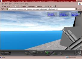
Overview: This model
was created as an individual project for Professor Don Brutzman’s MV-4204, VRML
course. All geometries throughout the
project are built 1:1 in meters as closely as possible with utilizing solely
open-source data for their construction.
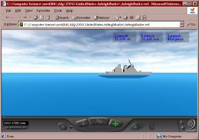
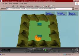
The primary file for the model is ArleighBurke.wrl, .xml, and
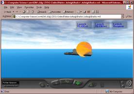
.html. It contains a simple control
panel/Heads-up-Display that allows the end-user to launch and view a harpoon
engagement of a generic Cruiser and two separate launches and engagements of
generic land targets by the Tomahawk Land Attack Missile. Known problems and areas for improvement are
stated in the appropriate section for the respective file in this document.
Designing the
Model(s): The primary source for all layouts and designs were obtained from the
Federation of American Scientist’s web page located at: http://www.fas.org . No restricted or classified data was used in
the development of the mode. Method
used to generate specific geometries was:
1) Break the item being designed into as many pieces as seemed
appropriate, 2) Trace the geometry of each piece on mk 1 mod 0 graph paper, and
3) decide between using primitive geometries, indexed face set, or the
extrusion node. Typically, a bright
color was used in the creation of all parts of the model to allow it to stand
out during the code/test/re-code phase of implementing the model design when
several other parts would already be present within the model. Only after 95 percent of the design for the
model was complete, did I learn that Adobe Photoshop 6.0, could take a graph
overlay and place it on-top of an electronic image, eliminating a lot of the
error from creating the model design by hand.
Animating the
Model(s): The first file animated while composing the Arleigh Burke mode was the
Propellers.xml/.wrl. The biggest lesson
learned in that endeavor was to keep the interpolators as simple as
possible. For example, to ensure a
smooth animation
Of the screws, I ended up using 3 angles, 0, pi, and 2*pi. Any greater combination and the animation
would appear to catch. The same concept
applied when animating the Harpoon and Tomahawk missile launches. The only time in general that I would add
another interpolator point in those scenes would be for a change in altitude of
the missile for the position and have a corresponding change in the attitude of
the missile as well in a separate orientation interpolator.
Another lessen learned
while animating missile launches with corresponding explosions was to use a
position interpolator to animate the scale of the missile so that after impact
it could be reduced to negligible size appearing to disappear with the impact
of the target. The inverse concept was
applied to the explosion files, they would begin at almost a size of 0, and
after the time delay for the missile flight path would then be triggered to expand
in size and then back to 0. Scripting
was used to effect a delay time for the explosions to begin, Cruiser to sink in
the Harpoon engagement, and to trigger the building explosions in the Tomahawk
engagements.
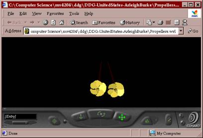
Fig
3, Propellers.wrl
Harpoon Prototype: Filenames:
HarpoonPrototype.xml, HarpoonPrtotype.wrl.
|
Fig4,
Harpoon Prototype |
Fig
5, Harpoon being Launched |
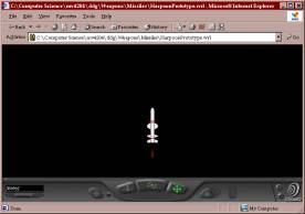
The first missile modeled in the Arleigh Burke project. Utilized FAS website exclusively with graph
paper to pull points for extrusions(missile body), and face-sets(missile
fins).
Known areas that can be
improved:
--Redesign Quad canisters. Ones
used are from the Cruiser model on Savage and are not built to scale resulting
in having to add extra scaling of the missile in the scene.
--Continue to improve the prototype interface to allow the end-user to
be able to send in times for the missile1.wav file to be played and fully
populate the 8 canisters with missiles.
--Look at collision detection for the missile so the explosion position
and timing does not have to be pre-scripted.
--Add animation of the missile going through the end of the quad
canister and of the booster falling away after launch
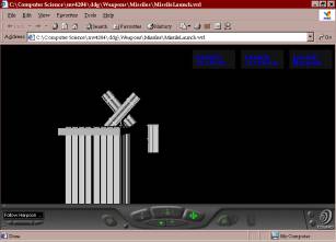
Tomahawk Prototype: Filenames:
TomahawkPrototype.xml, .wrl
|
Fig
6, Tomahawk Prototype |
Fig
7 |
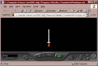
Last major work completed in Arleigh Burke model. Tomahawk/TLAM, is built to scale in meters,
and has internal fin animation that is completed within the first six seconds
of the missile launch.
Known areas that can be
improved:
--Same as for the Harpoon Prototype, continuing working on the proto’s
interface for the end-user. No scaling
issues with this missile since I designed the launchers from scratch.
--Can add a crane to each launcher, currently only contains a different
cell hatch where the crane would be underneath.
--Add more textures to the VLS launchers
--Add animation of the booster falling away in the booster-drop zone.
Missile Explosion Prototype
And Multiple Explosion Prototype:
Filenames: MissileExplosionPrototype.wrl, .xml
MultipleExplosionPrototype.wrl, .xml
|
Fig
8, Example use of MissileExplosionPrototype |
Fig
9, Example use of MultipleExplosionPrototype |
|
Fig 10, A few seconds later in a different
engagement (notice upper Building is already destroyed. |
|
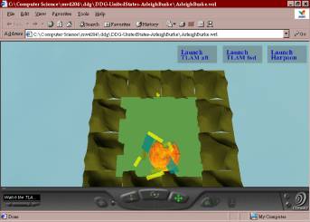
Uses explosion.png from the Pearl Harbor scene on www.planetnine.com for the image
texture in both prototypes. These files
were developed to be simple in nature after seeing that the complicated
explosions in the Pearl Harbor scene were 92 + pages of VRML that I would have
to suffer through to get a simple effect.
The Missile Explosion is triggered after a time delay, and is a simple
sphere that is scaled up and then backs to nothing with a corresponding sound
file. The multiple explosion prototype,
is the same just using three spheres triggered at different times.
Known areas that can be
improved:
--Continue to work on the interface of the prototypes to allow the
end-user to determine the texture file, sound file, and delay time.
--Incorporate with a collision-detection scheme to get away from the
scripting involved.
Arleigh Burke Gun:
Filenames: Gun.wrl/.xml
Re-used from the cruiser model on savage. Again had to deal with scaling issues from their model here. This would be the first item I would
recommend someone work on in the Arleigh Burke model in order to model ship to
shore bombardment.
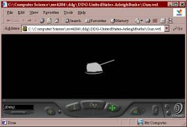
Fig 10, Gun.wrl
Arleigh Burke Flight Deck:
Filename(s); FlightDeck.wrl/.xml
Initially written as an extrusion. Changed to an Indexed Face Set in order to map the Flight Deck texture properly. Nets use the grill image from the VRML 2.0 sourcebook.
Nonskid is a picture of the road outside of the author’s house at Ord Military Community and then modified in Adobe Paintshop to add simple flight deck markings.
Known areas that can be improved:
--Redo the flight deck markings with greater accuracy from the drawings on the FAS website.
--Take a higher resolution image for the non-skid(maybe take an actual picture of nonskid on a ship).
--Add the slant to the flight deck. Possible now that it is an indexed face set, too hard to accomplish when it was an extrusion.
--Add the appropriate deck gear to the flight deck and other markings (HIFIR, etc).
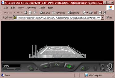
Fig 9, Flight Deck
Arleigh Burke Hull:
Filename(s): Hull.wrl/.xml
Contains the complete ship except for the ocean environment.
Known areas that can be improved:
--Do more justice to the angles on the hull. I’ve done what I could, but just figured out
a satisfactory technique at the end of the quarter when redoing the flight deck and fwd deck house to incorporate the array faces into the model.
--Smooth out the front of the ship.
--Add a sonar dome, rudders, deck gear, life lines, chaff launchers, torpedo launchers,
refueling at sea equipment, rigid-hull inflatable boats, intake/uptake louvers, pilot house glass, antennas, etc.
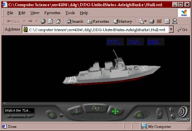
Fig 10, Hull.wrl
Conclusion: Found it to be a worthwhile experience creating a partially-physics(no formulas used for missile flight paths is why I say partial for now) based model of a warship that I commissioned as a junior officer. The biggest lessoned learned during the project was to determine early what level of detail/animation that I wanted to achieve as an “end-state”, and then get there and walk away from the model. If not, one can work forever on adding details, more accurate animations, etc. Next biggest lesson, was to pick a project early in the quarter and gear one’s weekly worlds towards this project. This approach enables one to created a fairly detailed and complex model while still doing your other course work justice.